For the final project that involves a CNC machine I stared first with the idea of an interactive puzzle based off one of my classmates that she in the pass has done work that it welcomes the viewer to participate. I tried designing one and I didn’t liked it is not really my style.
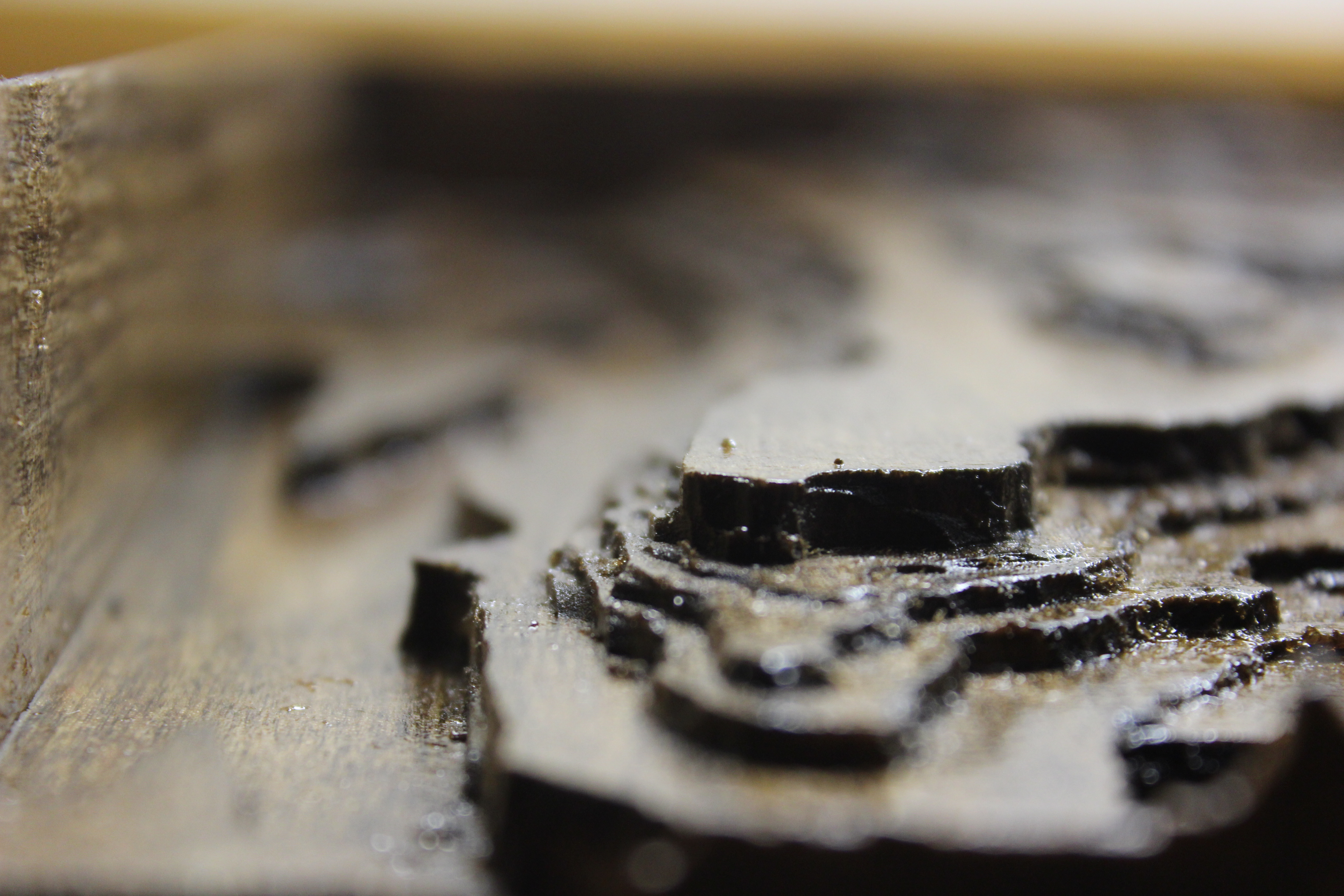
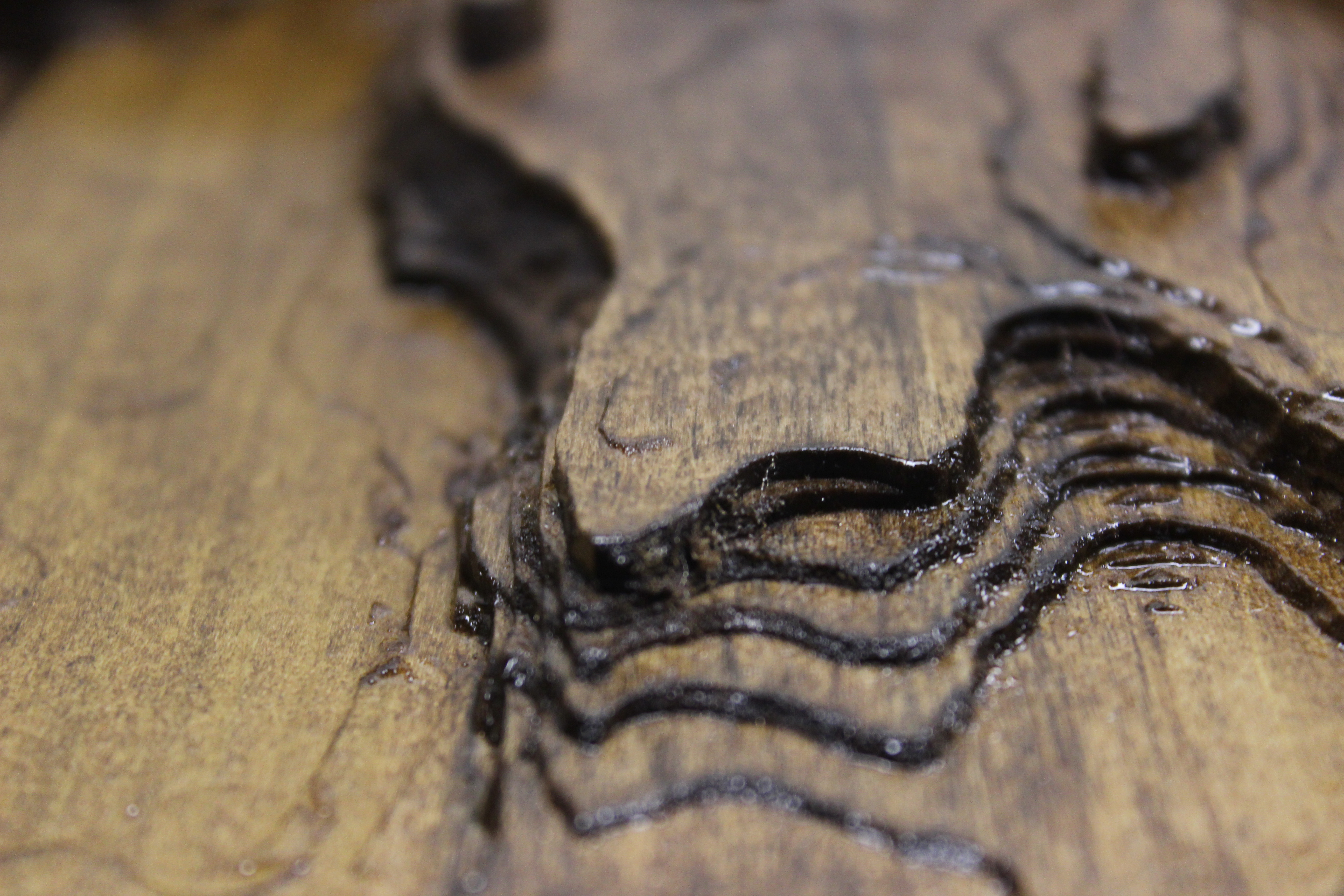
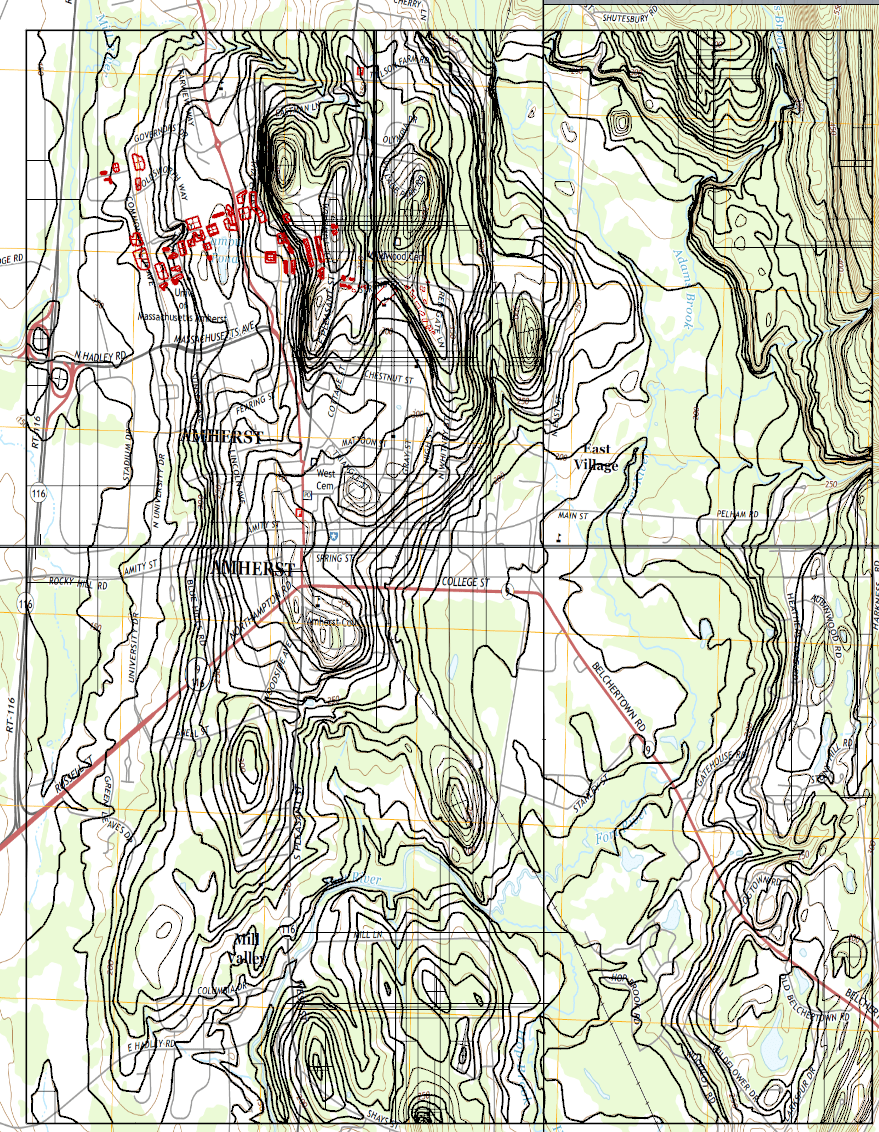
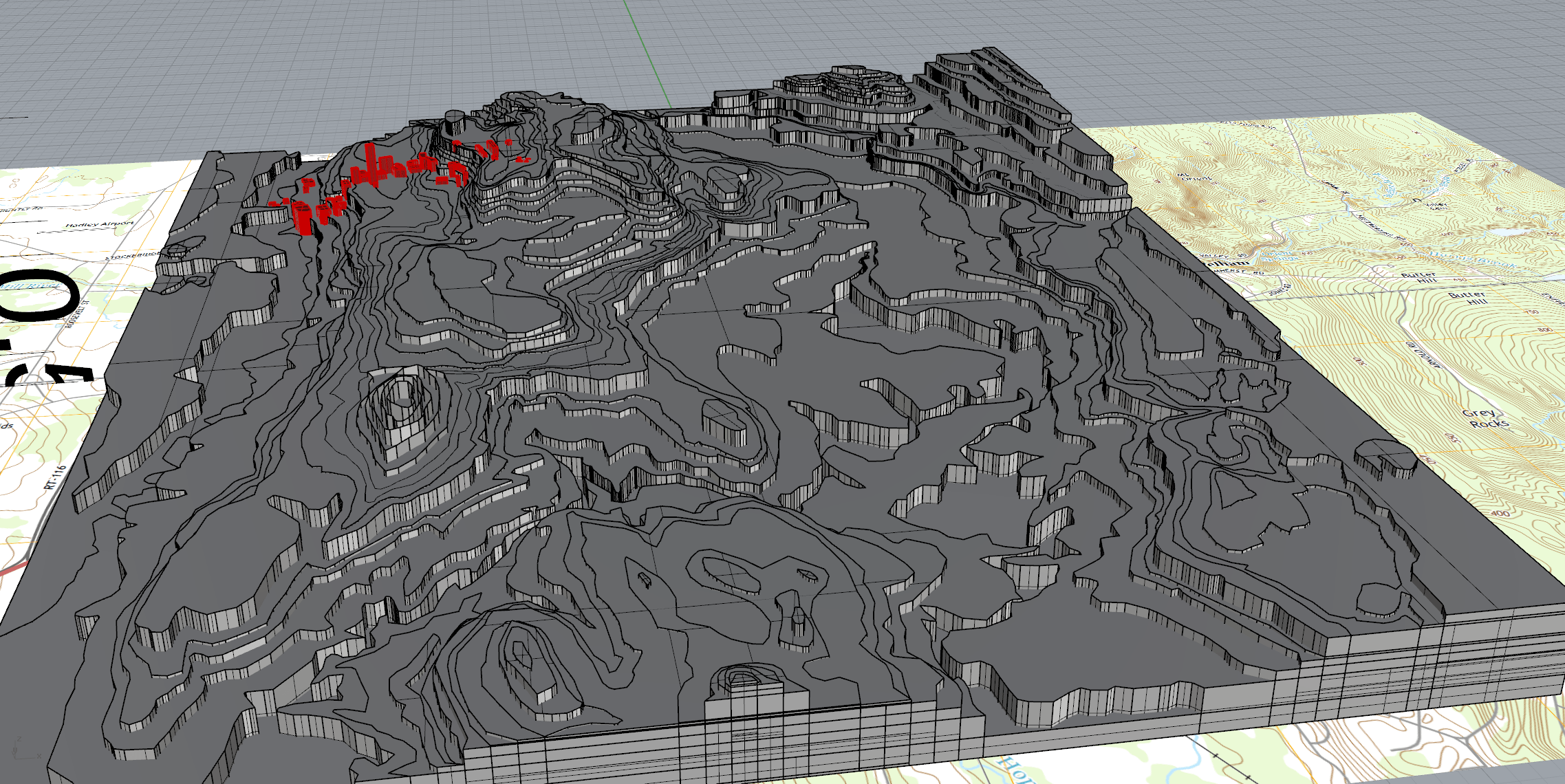
My roommate is a landscape architecture so I see a lot of elevation plans in my room, I decided to try to create a fictional landscape first with some futuristic ideas. It turned out good but it didn’t felt natural because it was a landscape that I made up. I then went to the USGS and looked up maps of different areas of the country. I decided to do a local area so people could relate more as my last project was a disaster for not able to relate to everyone. I took maps of the Amherst area and placed them as planes in the software. I then stared tracing all the elevation points within the boundary box that I created. I decided to take some liberties; everything goes up I didn’t made areas that go down which is not natural but instead I extrude them out upwards creating some slopes but it was something that was created naturally during the process. I followed a scale according to the height of the hills on the map. The maximum height on the map is 450 feet while the lowest is 100 feet. So every 50 feet is a grid point making the height of the point go according to the real world (technically only in the z axis) but also making it small as the maximum height doesn’t surpass 1 inch. I also was planning to make buildings but they would be so small that recreating them in the CNC machine could be difficult next to impossible because of the scale and how close most of them (like houses) the drill would probably destroy each one while creating the next one. Below are images of the project in the software Rhino.